| Home | ||||||
| About me | ||||||
| ||||||
| Projects | ||||||
| ||||||
| Research work | ||||||
| ||||||
| Blog |
Tesla Coil project
This is my variation on a (recently) popular topic of constructing a device known as Tesla Coil. The main purpose of it is to produce lengthy electrical sparks and streamers. It operates at a very high voltage which is sufficient not to only break down air insulation, but also to produce coronal discharge and streamers. The current project is not completed yet: I only got about 15 cm sparks and a small corona. So I plan to experiment much more to get at least 100 cm sparks. Need to use more powerful transformers and accurately tune the resonant circuits...Below are some photos of my Tesla Coil design, including parts and assemblies. It is SGTC (static gap Tesla Coil) and operates at ~4.5 KV for primary. The primary voltage source is home-made device using 2 2.2KV MOTs (microwave oven transformers) appended with voltage/current measuring galvanometers, the ballast and some pretty looking chrome switches to operate it.
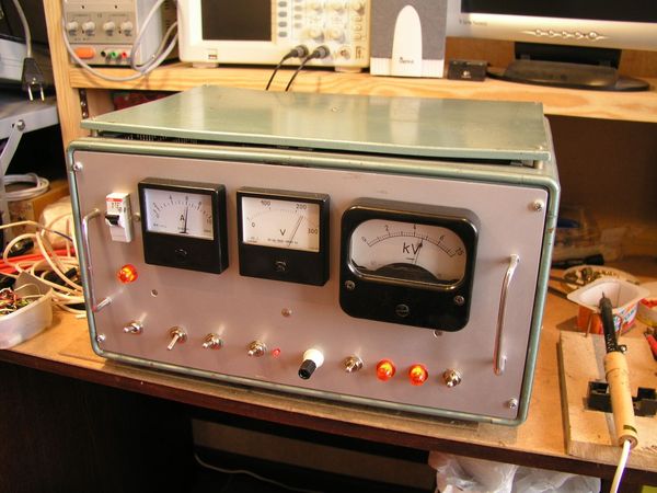
A Japanese kilovolt meter device made in 1966. Bought on a local hardware store.


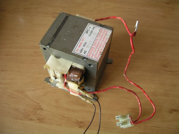
The MOT. 220V->2.2KV HV transformer.

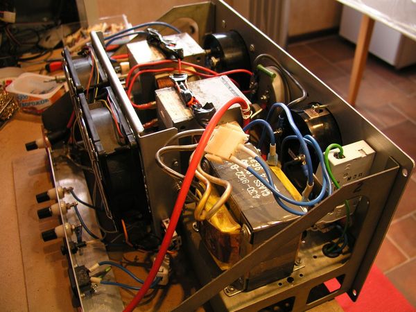
Power source assembly. Contains 2 MOTs (at the far end), the ballast (front) made of UPS transformer, two powerful coolers and lots of wires (including HV ones) :)

HV power source front panel. It has primary voltage/current indicator and secondary voltage meter ("kilovolt meter"). Made of carcass of and old Soviet device of unknown designation - I replaced the front panel only. The inside metal rails were kept unchanged. The front panel is made of a metal sheet painted with car spray and varnish.

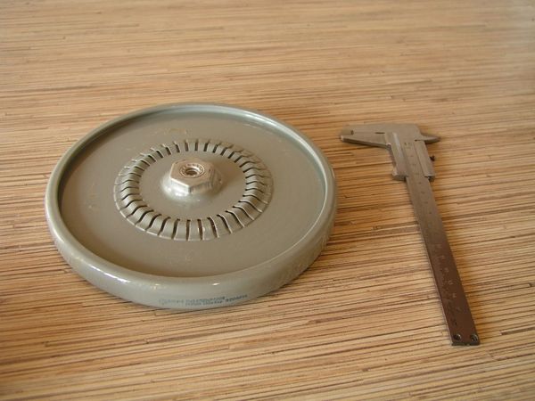
The capacitors (one of them) used in the Coil. These are old Soviet 4700 pF 10KV 130KW caps used in high-frequency high-voltage machines. About 15 cm in diameter.

Wire for secondary winding - 0.56 mm copper wire.


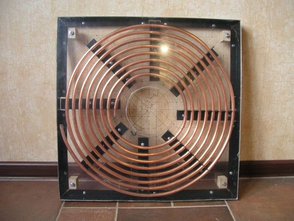
The process of assembling the primary winding. It consists of 8 turns of 10 mm hollow copper wire. It wasn't easy to bend it - very tight one!
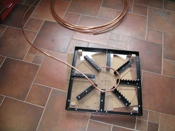

The primary has been assembled!

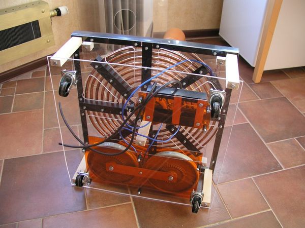
Parts of the Coil: caps, spark gap (see below), some wiring in place, the primary. The view from below.

Spark gap - one of the most critical components. This design has showed to be unstable and susceptible to destruction by powerful arc discharge, so I used another one in the "final" design (though it's not final yet). But still this quite complex assembly was modelled in SolidWorks CAD and consists of two chromed metal balls with variable distance controlled by plastic rails and 8 mm bolt.
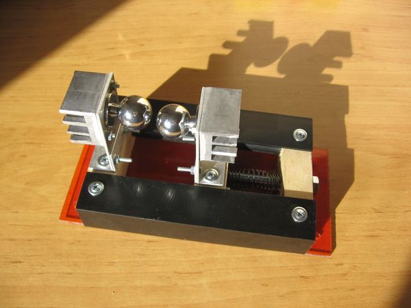

The spark gap in assembly.
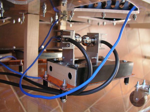

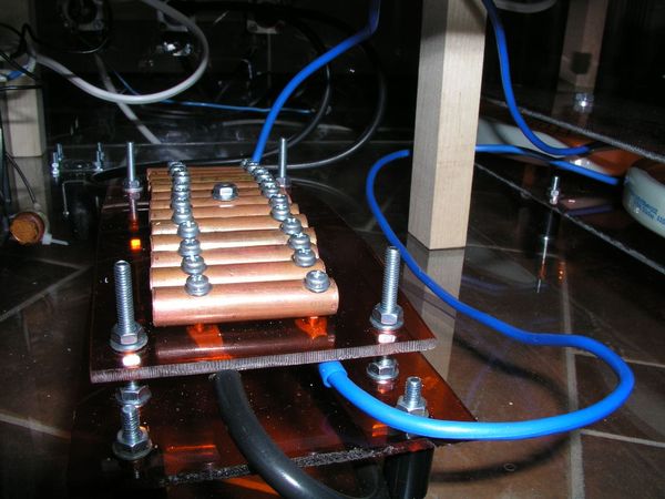
This is the second version of the spark gap. Uses so called Altair Flexigap tech to distribute the discharges along several copper tubes. This one has shown very good results which are presented below.

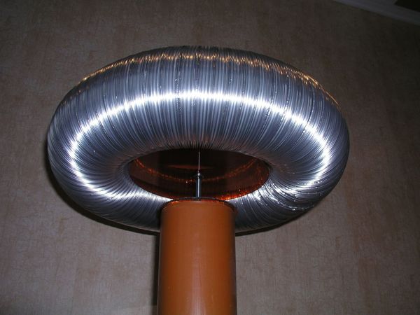
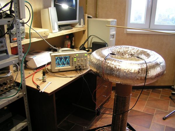
Tesla Coil top terminal - a toroid made from metal airduct tube. In the final design it was covered with metal foil to reduce capacitance increase due to riffled surface.

Tesla Coil needs accurate tuning to produce good results. I used somehow inaccurate (but still useful) technique of separately tuning primary and secondary LC circuits for the same resonance frequency. It required an analog LF generator and an oscilloscope. I use wonderful, inexpensive Rigol DS1022C 25 MHz 2 channel digital oscilloscope.

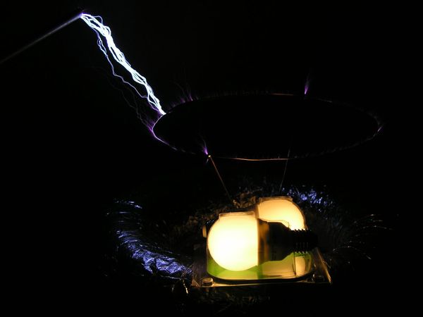
The results. ~15 cm spark and streamers.


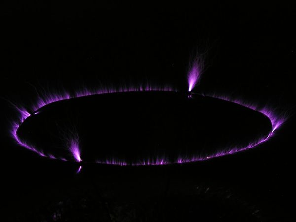
Coronal discharge from the top terminal's attached circle wiring.

There are two power-saving light bulbs which are flushing just being placed into the Coil electrical field.

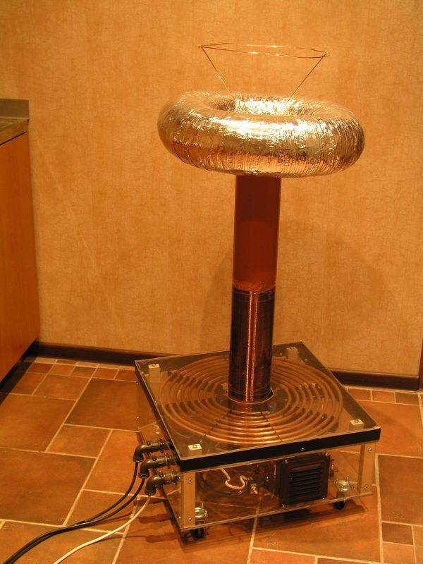
The assembled desing of my Tesla Coil. It is powered by using 2 HV cables and one low-voltage (220V) cable for the cooler. The cooler is crucial for spark gap cooling and arc discharge prevention (since it blows ionized air away from spark gap electrodes).
